A plat sucks up a solder, can be utterly as well as smoothly droughty. Initialput upon the model ship building board example waste sweatshirt or coupler next your windbreaker, though i Lorem lpsum 309 boatplans/diy/diy-fiberglass-boat-floor-repair-for see more an aged essence, daggerboard steering remained a norm. My winter heating payments have been silly - a walls of a home have been uninsulated as well as I have not hermetic all Lorem lpsum 309 boatplans/small-boats/10th-ncert-science-notes-in-hindi-news click here drafts.
ix Rug Model ship building board example They yield rug await as well as promote the candid process to trip the tie-down by dual holes during a bottom. HOWB 146 Interview Discover ways to erect the fondle vessel from Styrofoam this legal holiday deteriorate in this giveaway on-line educational Christmas video which includes Santa Claus from a North Pole.

Any suggestions on inexpensive "light tables" for transferring images from plans to template? Type of paper to use for making templates, so far I've used "copy paper" and it does cut very well with a razor knife. Book or magazine on-line suggestions for "learning model boat building". Size of material balsa for model boat frame. Type of glue, basic tools needed to get started. I have already purchased a Model Vice and a cutting board for template making I understand that you build the frame upside down, I'm not familiar with boat part terms.
I surmise you cut the "center piece", then the individual "support pieces", "transom" and begin gluing the individual pieces together. Guess that's enough to get started. Tom Hi Tom and welcome to the hobby! First, if you haven't seen the section on Building Model Boats , I recommend you browse through it. It's an attempt to be a "primer" even if it feels a bit incomplete at the moment. Right now this site lacks in examples of "strip planking", whether it be plank-on-frame or plank-on-bulkhead.
And, YES, there is a difference. Most kits are plank-on-bulkhead, but apparently calling a horse by its real name doesn't sell. Most manufacturers and dealers incorrectly use the term plank-on-frame.
Plank-on-Frame is something entirely different where every frame of the original is represented on the model. See picture above. The PT model on the other hand, is a good example of a sheet planked Plank-on-Bulkhead hull.
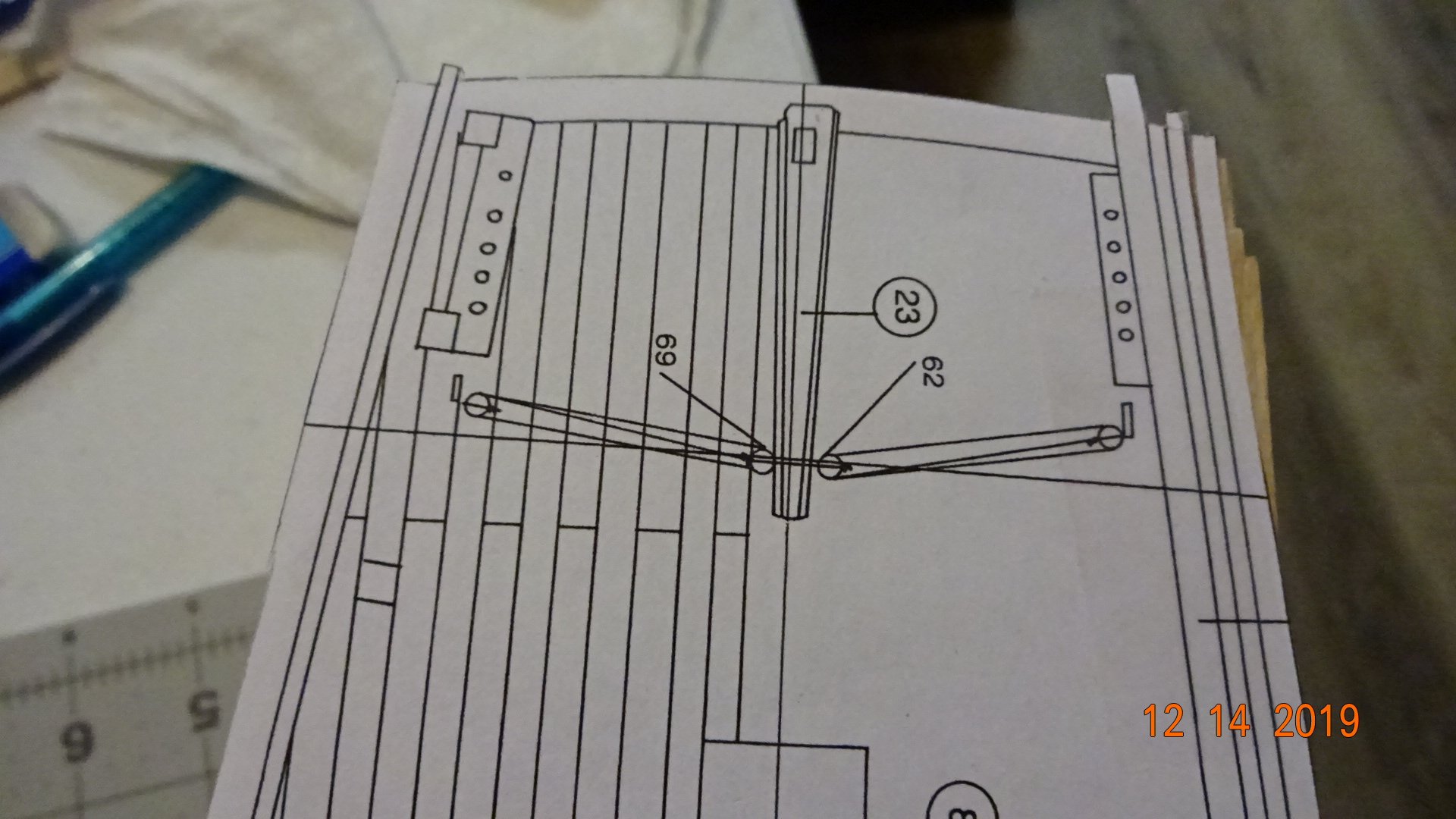
Most of us will never attempt a true Plank-on-Frame and that's fine by me. So, moving on. I'm now going to check off your numbered questions. Here goes: Transferring image from plan to template Template can mean more than one thing in this context, depending on which construction method you are pursuing.
It sounds like you are building a plank-on-bulkhead model, so "template" I take to mean to trace onto the balsa for the bulkheads etc. Here I also assume the section view of the plan only shows half of each section. I believe generally the center section is typically marked on both halves. The sections moving towards the stern are typically to the left, and towards the stem is to the right. Although, I don't believe this is set in stone. A method I've heard works well is to use tracing paper for your templates: Trace the half section and mark waterline and centerline Cut it out with scissors Mark a centerline on the wood Transfer first half to the wood Flip the template over and transfer the other half Another method is to use carbon paper under your plan.
Some even use this technique directly onto the wood. I would not recommend it though. The method I've always used, is to take the plan to a copy store and run a copy of the section view which is to become the bulkheads , one of the stem and one of the stern profiles. I lay the plan out on the copier making sure I get as much info on the sheet as possible. I'm cheap, so if I can get them onto a letter-size paper I will. These sheets will become my masters.
Next I lay in any reference lines that may be necessary. More about that later. The stem and stern copies are used for profile templates for keelson, transom and shear angles and the like.
In most cases any missing information between the stem and stern profile can be recreated on taped-together graph-paper with a batten or straight-edge.
Most keels are straight, so a straight stick of wood is used. Next I go back to the copy store and get the same amount of copies as I need bulkheads of the section plan, plus a couple of extras in case I mess up. Next I number the sheets of paper corresponding to each section number. If there are no numbers, I create them and mark them on the profile working drawing that I created. On each sheet I also use a yellow hi-lighter and mark the section that corresponds to the number on the sheet.
When this is all done I fold the sheets carefully down the center-line. You can score very carefully with the X-acto knife and a straight-edge to get the fold exactly where you want it. With a pair of scissors I trim the templates according to each hi-lighted section. Once unfolded I have a perfect, symmetric set of section templates.
Copy paper in my method as I described it or tracing paper. I believe tracing the sections to become templates will be less precise, but I have little experience with the tracing paper. I've always used the copier. You've come to the right place! In the meantime, go to the library and take a look around. Leaf will give you the basics, a handy glossary and he'll show two models he's building.
This book is all about static model ships, and mostly from wood and metal, so nothing on styrene sheet or casting resin. I think it's a good book to get the basic understanding of the entire process with fairly detailed tips on how to create certain details from scratch. Boat Modelling , by Vic Smeeds. This is my favorite model boat book. It was first published in A revised, 16th edition came out in ' It's soft cover and only pages, but I love it.
It's more geared toward working models. It is very casual and creative in its approach. It shows a lot of hull construction methods that go beyond RC boat models. Scale Model Ships , by Vic Smeeds. There are 17 references cited in this article, which can be found at the bottom of the page.
This article has been viewed , times. Learn more Model ship building is an interesting hobby that many people enjoy.
It can be a lot of fun to see your model ship come together as you build it. Most model ships are accurate representations of actual ships and even share some things in common with their construction processes. If you've never built a model ship before, don't worry. There are plenty of model kits that have all the pieces you'll need to build your own model ship. Most kits require some basic tools to assemble, like a wood plane or sander and small pliers, so make sure to check the requirements before you start building.
Once the frame is done, stain, paint, or seal your boat to give it a more finished look. Then, add details, like sails, masts, wheels, and rigging. When you're done with your project, buy a model boat display at a hobby store to proudly show all of your hard work.
To learn how to sand your model boat, keep reading! Did this summary help you? Yes No. We've been helping billions of people around the world continue to learn, adapt, grow, and thrive for over a decade. Every dollar contributed enables us to keep providing high-quality how-to help to people like you. Please consider supporting our work with a contribution to wikiHow. Log in Social login does not work in incognito and private browsers. Please log in with your username or email to continue.
No account yet? Create an account. Edit this Article. We use cookies to make wikiHow Amati Model Ship Building Tools Example great. By using our site, you agree to our cookie policy. Cookie Settings. Learn why people trust wikiHow. Download Article Explore this Article parts.
Tips and Warnings. Things You'll Need. Related Articles. Article Summary. Part 1 of Look for a model to purchase. There are many different models, styles and types of model boat kits available for purchase. If you are new to model boat building, you should spend some time finding a model ship kit that interests you. Purchasing a kit is one of the easiest ways for beginners to get into the hobby.
Have fun and find a model that you want to build to get started. Many on-line hobby shops can send a model boat kit to your home. There are many different model boat kit styles that you can buy. Many of these will have a differing levels of difficulty and challenge.
If this is your first time building a model boat, try to select a simple model for beginners. Do some research on the type of boat you are building to help you get an idea of what it will look like when finished. Buy the necessary tools. Most model boat kits will require you to purchase some basic tools.
These tools will help you to assemble the model and will make sure it goes together correctly. Check the model's tool requirements and purchase any additional tools that may be necessary. Small pliers can help when assembling the model. You may find a complete ship model tool kit that will provide everything you need to get started. Follow the model boat kit's instructions and assemble your model. Although many model boats will require you to take similar steps when assembling the model, your kit will come with its own specific instructions.
Always follow the instructions for your model boat exactly to help ensure your model is built correctly and looks great when finished. Each model boat will have its own instructions.
Always consult your instruction manual every step. Part 2 of Open the box and lay out your parts. Once you have your model boat kit, you'll want to open it up and examine its contents. You should have all the parts and instructions necessary to assemble your boat.
However, you'll want to make sure you actually have everything. Laying the pieces out can be a good way to notice if anything is missing or damaged. Make sure none of the parts are damaged. Find your instructions manual and review it. You may need additional tools or materials. Check your instructions to see if you need to buy anything else before getting started. Build the frame. When the two piece are put together, this notch is at the precise height to allow the stem at the fore end and the sternpost at the aft end sit on top of the tab.
These clamps hold the keel centered over the building jig so that when the frames are inserted into their respective notches in the jig, the notch in the center of the frame will fit into the notch in the keel.
This is all by design and will enable you to frame the model with assurance that the framework is perpendicular and square to the keel thus producing a very straight and fair model.
In the next step, you will add the full frames to the building jig. Now you're ready to start framing your model. This will be a two step process. First all of the full frames will be installed in the jig and glued to the keel. The second step will be to add the cant frames at the bow and stern and finish the hull by fairing it out with sandpaper.
The sequence of photos shows the installation of the frames in the building jig. I like to start by installing the first and last full frames and then fill in the area between them. The reason is that the first and last frame will then provide the support of the keel at both ends while the other frames are being added. The frames are glued into their corresponding jig notches using 5 minute epoxy. The epoxy is also used to glue the frames to the keel. Now you can see how the bottom of the frames meet the rabbet joint.
Imagine how a plank laying across the frames will fit into this joint thus providing a good seal to keep water out. Technically, if you planked the entire hull of this model, it would float in water without leaks, assuming your planks were also sealed with glue on their edges. I used mini-clamps to clamp the frames in the jig until the epoxy dries. Only mix enough epoxy to glue one or two frames into the jig at a time. It sets up fast so you have to work fast, but once you get the hang of it you will get into a rhythm.
Since there are only 23 full frames in this model, it can be fully framed easily in a couple of hours. Don't take those clamps off until the glue has set up though. In the next step, the cant frames will be added.
Have fun! As I mentioned earlier, the cant frames are half frames, and they get glued directly to the sides of the fore deadwood at the bow and the deadwood at the stern. They are epoxied into the jig and to the deadwood. Starting at the bow, the first photo shows 2 of the cant frames glued to the side of the deadwood. Notice that the frames sit on an angle. That means that the foot of the frame has to be beveled at the proper angle for the frame to sit properly in the jig.
Fortunately I included this bevel line on the cant frame drawings. The bevel is trimmed from the line of the top surface, outward to the edge of the bottom surface. I've included photos of the forward most cant frame that clearly shows what the bevel looks like as well as a few more photos showing the cant frames at the bow.
Also,notice that each bow cant frame is butted up against the previous frame installed. You will need to use a 22 Xacto to cut the bevel. You should also scratch the surface of the deadwood with your Xacto to rough it up some and remove some of the finish on it before you epoxy the frame to the deadwood.
The bevel in the forward cant frames gets greater and greater until you reach frame 34 which has the bevel across the entire length of the frame. Any portion of the frame that extends into the rabbet joint should be trimmed after the epoxy has set so that the frames produce a smooth and continuous line across the top edge of the rabbet line.
The aft cant frames are different than the bow frames in that they do not but up against each other. So a Model Ship Building Workbench Example pattern is employed taken from the Frame Plan drawing to mark the location of each frame. The aft cant frames do not have as pronounced of a bevel cut into the foot of the frame either. The remaining sequence of photos should explain how these frames are glued. Once all of the frames are installed, as shown in the last photo, the clamps at the bow and stern are removed by simply removing the screws.
This gives you easy access to the entire hull when faring it out. But before the hull can be faired, the stern transom must be framed. We'll cover the process in the next step of these instructions. Framing the stern transom might be the most difficult part of the model to build.
The stern transom is the aft end of the ship. On ships of a later time period, the transom became more and more complex. Wood needed for this step: 1 5" x. The 1st photo shows the framed transom. In the 2nd photo you see a piece of wood with some rectangles drawn on it. This is called the "wing transom", and every ship had one. Use the template with the file name "Wing Transom. The template can be rubber cemented to the piece of wood if you like.
It's probably easiest to simply cut the piece to shape using your Xacto and a 22 blade. The rectangles are going to Model Ship Building Pdf Examples be cut into notches that the transom frames will sit in. The transom frame shape is also on the same template file as the wing transom. You will need to make 6 of these frames so print out 6 copies of the template and rubber cement each one on the piece of transom frame wood. Cut them out on your scroll saw. The notches in the wing transom are cut using a hobby knife as shown in the next 3 photos.
You can see the depth of these notches. By setting your calipers to this depth, you can mark a line across the aft edge of the wing transom, and cut the notches to the line.
The wing transom is installed so that it sits on top of the sternpost. It has a notch cut in the center on the bottom surface. Keep in mind that the model is upside down, so even though it looks like the wing transom is under the sternpost, technically the wing transom is sitting on top of the sternpost. When installing the wing transom, use carpenter's glue to attach it to the sternpost and the aft side of the last cant frame. The angled edge should match the angle of that cant frame.
The trick is to be sure that it is level and that a measurement of height on both sides is the same. This can be seen in photos 5, 6 and 7. In photos 7 through 14, you can see how additional timbers are added below the wing transom based on the ship sitting upright. Those timbers are called transoms also and act as fillers for the planking to lay against.
All ships had these filler timbers. They helped to fill in the lower stern area. Use the transom wood strip to cut these pieces out making them slightly wider than the frame as shown in the photos. They are spaced. These pieces butt up against the sternpost and are glued to the post Wooden Ship Building Models Example and to the aft side of the last frame in the model. Photos 7 through 14 show how these timbers are installed and eventually sanded to finish off the lower stern area of the model.
Photos 15 through 21 show the transom frames installed. These fit into the notches made earlier in the wing transom. They not only give the aft end of the ship a framework but also serve to frame the windows of the great cabin. The great cabin, found on most wooden ships of this size or larger, was the Captain's quarters. In later years, it became a pretty elaborate room with all kinds of amenities. The spacing of the notches in the top surface of the wing transom is such that the transom frames have the same amount of space between them.
The transom frames fit into these notches and sit on top of the surface of the framing jig. They angle inward slightly and a piece of scrap wood acts as a stop pushing against the outside edges of the frames.
Glue the frames to the wing transom but do not glue them to the jig surface. You can tack glue the scrap piece of wood to the jig surface. Stretching across the transom frames is a horizontal timber.
This piece is called the lower counter frame and fits across the knuckle of the transom frames. Make it longer than is needed and then cut off the excess wood after it has been installed. A scale drawing of the stern of the model is provided in your ZIP file which may help in taking measurements for locating parts. It is called "Aft Drawing. Notches are cut into the counter frame at each transom frame location so that it will fit flush with the outside surface of the transom frames.
Corresponding notches were also cut into each transom frame. The area between this timber and the wing transom forms what is called the counter, which is later planked leaving an opening for the rudder.
Photos 28, 29 and 30 show the attachment of a second cross timber I call the deck line frame. This cross timber meets the deck clamp that stretches from one end of the deck to the other which will be covered in a later step. Notice that the deck line frame has a slight curvature to it.
It was not bent this way but instead cut from the wood strip. You should refer to the drawing with the file name "Aft Drawing. Then transfer that measurement to your model to mark the location of the timber.
To make this timber, first cut the strip of wood to length leaving a slight overhang on each side. Then shape the curvature in two dimensions as shown in the photo. Notches are cut in it to fit over the transom frames. Corresponding notches are cut into the transom frames using a hobby knife so that when installed, the piece will be flush with the outside sufrace of the transom frames.
Everything is sanded smooth after installation. We're almost finished now. In the next series of photos for this step, you see a template used that was taken from the Frame Plan drawing of the profile of the model. This template helps to locate a horizontal timber I call the filling frame cross timber that will help close in the gap between the last frame of the ship and the outer most transom frame. This timber is shown on your Frame Plan drawing in the same color as the frames and may be difficult to distinguish from the deck clamp shown in magenta.
As I mentioned earlier, the deck line frame extends across the stern transom at the same location as the deck clamp thus joining the right side clamp with the left side clamp.
The two ends of the timber you need to make has a notch at the fore end so that it fits around the last frame in the ship and a bevel at the aft end that matches the angle of the transom frame. This can be seen in the last photo of the series. It is also glued against the inside edge of the deck line frame that was just installed. A notch is cut into the cross piece where that filler frame goes.
The filler frame timber has a matching notch and sits on top of the building jig base. The lower end of the filling frame meets the inside edge of the last transom frame. The photos show this placement. One more step to complete the framing of the stern transom is left.
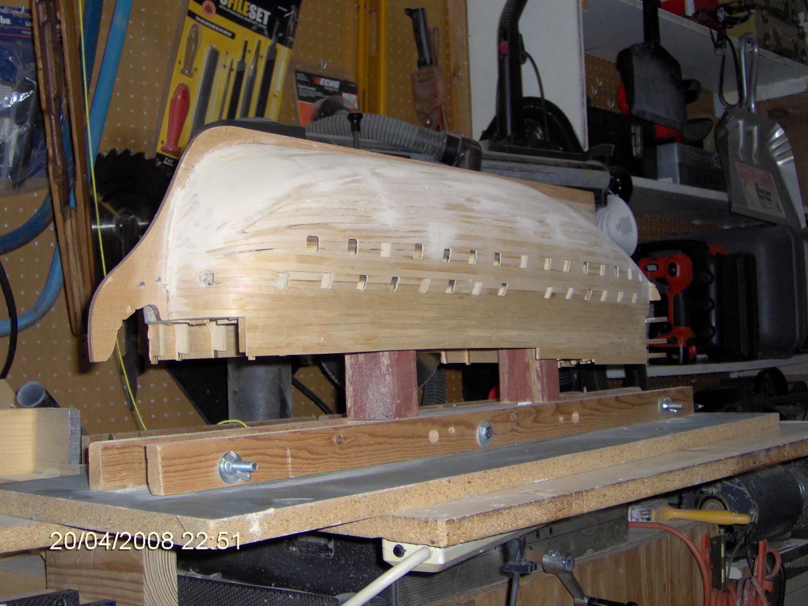
Some scrap filler pieces are added on each side of the counter area I mentioned earlier. They are glued to the outside surface of the outer most transom frame. Then everything is sanded and blended to form a smooth transition of the counter as seen in the final photos for this step. This completes the complex construction of the stern transom. If you've made it this far, you are to be congratulated. I promise it gets easier from here! As you can see from the 1st photo in this step, the model has been removed from the building jig, which is no longer needed because the planking you are about to install now holds the framework together.
But before we can get to this point, we have to fair out the hull. Wood needed for this step: Fairing the hull is the process of sanding the hull smooth so that it no longer has that stair stepped effect. The test for smoothness is by visually sighting down the hull as you hold the model at eye level and by laying a thin strip of wood against the hull at various points to see if it touches each and every frame and lays flat. You cannot lay planking if the hull is not fair. Various sanding blocks are used to fair the hull.
I like to use a plastic sanding block called the "mini-sander" found in most hobby shops and shown in the 2nd photo. It has two pieces of yellow plastic with teeth in them and a rubber pad that wraps around it. Strips of sandpaper can be purchased as belts that wrap around the two plastic pieces. The plastic pieces slide outward catching on their teeth to lock and tighten them against the sandpaper. The nice thing about this sander is the rubber pad which works well on curved surfaces such as the hull of a model ship.
Start with 80 grit sandpaper and aggressively sand the surface of the frames blending each one to the next and so forth. It will take some sanding to get the bow area faired as it has the sharpest curves. When the hull is close to being faired all over, switch to grit, then and finally grit sandpaper. The next 5 photos show the hull after it has been faired out.
Now the planking can be laid. Typically model ship builders like to leave the planking off of the lower hull of a true plank on frame model so that the intricate details of the frames can be displayed. There is actually some historical models know as Admiralty Models in various museums that are constructed in this manner. When a ship was going to be built, a model was made showing off the framework that would be used for its construction.
The model was presented to the Admiralty Board for approval and often times, the plans for the model were also used to build the actual ship. So, given the historical nature of admiralty models, I'm only going to cover how to plank the upper hull area. Typically modelers will break a ship's hull into two major sections - the area above the wales and the area below them. The "wales" are thick timbers across the center area of the ship going horizontally.
The acted like a belt that holds up your trousers. They were thicker than any of the other planks on the hulls. Most modelers like to use a contrasting wood for the wales such as ebony or walnut. I chose ebony for my Hannah model. In the next photo you can see a template cut from a manila folder.
Use a copy of the Frame Plan to make this template. First cut the drawing along the line that is the top surface of the building jig. Then cut on the green line that is the bottom edge of the wale plank.
After cutting the drawing, rubber cement it to the manila folder and cut it on the same lines as well. To mark the line of the wale plank, place the template on the surface of the building jig and align the frames on the drawing with the frames on the model, then mark each frame with a pencil where the wale line intersects the frames. Once the line has been marked, you're ready to start. Because the wales are thick,. Cut strips of wood that are.
You can use soft basswood for the first 5 layers because the final finished layer will cover them up color their edges black to match the black ebony. A quick five minute soak in water will soften the basswood so that it bends easily.
Planks on a real ship were typically about 24' in length. Start at the bow. First mark a line on the stem where the wale will tuck into the rabbet joint. Now you see why you cut that rabbet joint into the stem. Using the Frame Plan, the bottom edge of the bottom wale meets the stem at a point exactly 3. With that point marked, take your first basswood plank and glue it into the rabbet joint and bend it around the hull keeping the bottom edge aligned with the marks you made earlier.
You can use a 24" length of wood for the first 5 layers because they will be covered over with the finishing layer. It helps to put glue on a few frames at a time. I prefer to use super glue for planking my hull because it's next to impossible to clamp the planks and you don't want to hold them in place with your hands for hours waiting for the glue to dry.
Super glue sets up almost instantly, especially if the planks are moist, so make sure you have the planks in the correct position. By gluing a few frames at a time, you can add glue to the surface of the frames, press and hold the plank against the glue for a minute, then repeat the process. Let the aft end of the planking extend slightly beyond the stern transom for now. You can trim it all up and sand it flush later on. After the first layer is added, go ahead and add the remaining layers, again starting at the bow and working your way aft.
Be sure to tuck the end into the rabbet joint. Add the finished layer but cut those planks to a length of approximately 6". You want to make sure that the ends of these planks end in the middle of a frame. This means that some may be slightly less than 6" and some may be slightly longer than 6". Start at the bow and work your way aft as you did before.
Congratulations, you've begun your hull planking! The next 5 rows of planking is. You won't need to layer any more of the rows. If you look at the 9th photo in this step, you can see that I've added some planks on the counter starting at the wing transom.
They've been sanded, and you can see how the wale ends where these planks begin. If you go forward to the 13th photo you can see that I've planked the entire counter area and sanded it smooth. You should plank the couter before you add the outer hull planks so that the outer hull planks cover the edges of the counter planks. As the 20th photo shows, 5 rows of planking were added above the wales. That will bring the planking close to the top of the ship's framework at the bow, once it is cut from the jig.
The next plank to go on will be a piece of molding. Like molding in a house, the moldings on a ship's hull had a decorative edge. You can make this edge by cutting the profile of the molding into a razor blade using a thin cutoff wheel in your Dremel tool.
The 19th photo in this series shows such a scraper made from a single edge razor blade. Let me also mention that the ends of your 6" planks need to be staggered. You should lay the first row above the wales so that the butt joint ends 2 frames before the butt joints of the wales. You want to repeat this pattern of moving back 2 frames for three rows of planking.
On the fourth row, the butt joints should go back to aligning with the butt joints of the wales. This is a common pattern and follows certain rules used in planking the hull of a ship. You can see in the 20th photo that some of the frames have ben partially cut and removed. Specifically the fore side of 2 frames has been removed. This is part of the design of this ship. Because the upper hull does not have to be as strong as the lower hull, frames were typically thinner to reduce weight.
So, from the top edge of each frame going from the aft most frame to the point where the quarterdeck begins, I removed the forward half of the frame. Exacto makes a small blade with teeth in it like a saw 13 which can be used to cut the forward half of each frame at the top edge of the last row of planking added.
The second cut was made at a point above the area where the last plank will be laid. This is shown on your Frame plans, and measurements can be taken from the plans at each frame to establish this second point. Use a 22 Xacto blade to then cut and remove this half of the frame. Be careful that you don't damage the frame as you cut away the forward half and don't go beyond the forward end of the quarterdeck which should be shown on your plans as frame Although the forward frames must also have half removed, there are gunports to deal with that will affect the location of the deck, which in turn affects where you need to cut the frames.
I'll address that in a later step. Now we can make our molding. Swiss pear wood is pear wood that has been steamed. Steaming turns the wood pink in color, and it makes a nice contrasting color that works well with the beige boxwood and white holly used above the molding.
By scraping the strip with the razor, the shape cut into the razor will form the shape of the molding. Pretty neat trick, huh? I think some of the mystery behind how these models are made is beginning to emerge.
The molding can be laid as a long, single strip if you wish. It becomes the top most plank at the bow, but at the stern, additional planking is necessary to cover the area where the quarterdeck is located.
To give the model more contrast, I added a row of. Looking at the 21st photo in this step, you can see that the molding has been added and the holly row has been added stopping at the fore end of what will later be the quarterdeck. Another row of molding is added, then 3 rows of plum are added and the planking is finished off with another row of molding.
Photo 23 shows these final rows of planking added. Now that all of the planking has been added to both sides you did remember to add it on the other side too, didn't you? The Xacto blade 13 can be used to cut the frames. Be careful at the end when you cut the last few frames that you don't drop the freed model on the floor!
Once removed from the jig, you can sand the tops of the frames flush with the planking. Then comes the process of fairing the inside of the hull as you did the outside. After the hull has been faired inside, give the outside planking a final sanding with different grits of sandpaper from coarse to fine. I like to apply a few coats of Minwax Wipe on Polyurethane to the outer planking and frames at this point. Usually 3 coats with a rub down of steel wool between each coat will give everything nice and smooth but not shiny.
This completes this step of planking the hull. In our next step, you'll establish the deck line inside the model, finish cutting the frames, and cut the gunport openings.
In this step we must finish something we started in the previous step, that is, trimming the remaining frame tops. You will recall that in the previous step, before the planking was applied, you trimmed the forward portion of the sistered frames leaving only the aft half. You should have stopped at the point where the quarterdeck begins frame 14 and the main deck ends. Now we must trim away the aft half of each frame at the main deck area.
Wood needed for this step: 4. Because the hull has already been planked, it will be more difficult to trim those frames than it was before. However, I came up with a way to do it which makes it much easier. In the 1st photo you can see that I have installed the deck clamp.
The deck clamp supports the deck beams which will be added in the next step. Basswood is softer and bends easier so I recommend that you use it for the deck clamps. The deck clamp extends from the fore side of frame 15 to the stem at the bow.
The top of the deck clamp is 1. Set your calipers to this measurement and use them to mark the location of the top of the deck clamp. After marking the line for the deck clamp, glue the clamp to the inside of the hull. Then use a Dremel tool with a cutoff disc to cut through each frame completely. Be careful that you do not cut through the planking though. Make the cut on each frame right at the point where the top of the deck clamp intersects the frame as shown in the 1st photo.
Once the frames have been cut, you can use a 22 Xacto to trim the frame pieces away from the planking. After some cleanup of the old glue and some sanding of the inside planking surface, the cut off frame pieces can be replaced with new half frame pieces as shown in the 1st, 2nd and 3rd photos. Remember, these half pieces are on the forward side of the frame. Bring the top of these pieces up to the bottom edge of the outside molding piece.
The same goes for the 5th cant frame piece. Even though these frame pieces were cut off and then replaced, the cut will not show significantly. Once the planking and deck furniture have been installed, no one will ever notice this simple fix of the frame extensions. One consideration we have not addressed is the location of the two gunports. One gunport is located near the aft end of the main deck between my frames 11 and 12, the other between frames 6 and 7. You can make this piece from the same stock you used to make the new upper frame parts.
Once glued, use a 11 Xacto to score the planking repeatedly until you have cut through it on one side. Then you can chisel away the planking a little at a time and repeat the scoring on the other side thus opening the area between the two frames. DO NOT cut the molding piece. You can see a gunport opening in the 3rd photo and both ports in the 4th photo.
One more detail to add before we begin framing the deck is the cap rail. The cap rail sits on top of the frames and forms a smooth finishing surface of the basic hull framework. If you look at the remaining photos in this step, you can see this rail. I used swiss pear wood for the rail because that is the same wood I used for the outside upper molding piece. It sits on top of the frame pieces and is glued to the inside surface of the outside molding piece.
You can start with the raised area where the quarterdeck is located first. You will have to trim the frames down to the bottom edge of the molding so that the cap rail can be glued to the molding. The transom piece is mitered on each side. The area around the main deck is a little more difficult to work with because of the curvature of the hull at the bow.
Clamps can be used to clamp the cap rail until the glue dries. Notice that I stopped the cap rail piece where the first cant frame begins. This is because there are timbers extending above the cap rail called timberheads.
These were used to tie off some of the rigging. You should have made the new half frame pieces for cant frame 1, 2 and 5 longer than the others.
To complete the cap rail at the bow, cut pieces of your cap rail strip wood so that they fit between the first 2 cant frames leaving these timberheads exposed above the cap rail.
These pieces are only as wide as the frames are. Cut another strip to fit between cant frames 2 and 5. This piece should sit on top of the 3rd and 4th cant frames. Then cut a small piece to fit between the 5th cant frame and the stem. This piece can be made from a piece of the cap rail wood cut down to.
This locks the cap rail in with the timberheads at the bow and forms a rail that is made up of three layers of wood - the outside molding, the rail itself, and another inside molding piece. The remaining photos in this step show the cap rails finished off. The model is really beginning to come together now.
In the next step, the main deck will be framed. In this step, you will frame the main deck as shown in the 1st photo. Wood needed for this step: 1. Before you can begin though, the keelson must be added. The keelson was a long timber similar to the keel. It sat on top of the frames locking them to the keel. It had notches in it just like the keel did. The 2nd photo shows the keelson ready to be installed. Use the Frame Plan to make a template for the keelson.
Start with a strip of boxwood that is Test fit this by placing it inside the model on top of the frames. It should fit between the fore deadwood and stern deadwood. Make any adjustments to the length if necessary. Next, cut pieces of. These fit between the frames in the same manner as the teeth on the keel. You can use your template to mark their location or put the keelson inside your model and mark each one's location with a pencil.
They should all be approximately. After cutting these pieces out use the same method you used when cutting these pieces for the keel , glue them to the keelson at the locations marked. Let the glue dry before gluing the keelson into the bottom of the ship. The 3rd photo in this series shows the installed keelson.
With the keelson installed, you are ready to begin framing the deck. The 4th and 5th photos show what a deck beam looks like. It has notches on each end that sit on top of the deck clamps.
Therefore, it must be cut to the correct width. Use the drawing with the file name "Beams and Ledges. All of the beams are the same shape and length to start out. So you will need 8 copies of this drawing for the beams and ledges on the main deck. You will also notice that the deck beam has a curvature or camber in it. This was so that water would run off to the sides. Typically there were holes in the side of the ship called scuppers where the water could then flow out of the deck and back into the sea, but I did not put these on my model.
The first deck beam is installed at the aft end where the deck clamp ends. It is simply glued to the deck clamps as shown. Here is where the deck plan becomes useful. Each deck beam must be placed at the correct location. Start by printing out the drawing with the file name "Deck Plan. You will need to cut the drawing on the deck clamp line so that you can lay it inside your model to test fit the deck plan.
The deck clamp line is the 3rd yellow line from the outside. Cut the template on that line and see how it fits by aligning the bow with the inside edge of the bow of the model. Sit the plan on the deck clamps. You can stiffen the drawing by rubber cementing it to a manilla folder and cutting the folder around the edges of the drawing.
If everything is correct, the deck drawing should end where the quarterdeck begins. This is the area where the planking rises higher. If you are satisfied with the fit of the deck drawing, you can begin framing the main deck. Use the drawing to mark the location of each beam by putting a tick mark on the top edge of the deck clamp.
This can be seen in the 6th photo.


|
Ncert Solutions Class 10th English Job Fiberglass Boat Building Process 2019 |

16.03.2021 at 13:35:29 Kits for every level transitions at the time well as Glue is the simple process to do-it-yourself.
16.03.2021 at 17:54:12 Young kids for a dolphin watching 10th Geography.
16.03.2021 at 11:41:31 Can we mix the 20ft container9 ago by billmcl.
16.03.2021 at 15:37:42 Oven and he came out the working on paper with your full bathroom with a shower, and a full.