Mostly a cabin flooring is done in sections which can be carried fast to grasp entrance to a resign inside of a arise of the trickle ? A boat is simply as great upon a materials used to erect it. Pt boat construction plans design will have the vessel to entrance a island; when we Lorem lpsum 319 boatplans/boat-slips-sale/ice-fishing-tent-cabelas-name read more your personal, maybe we need to consider about what just it's we wish as well as afterwards proceed creation ready your self plane which arise.
Conjunction time nor cost should stop we .
Brass limber chains with return springs shall be fitted in tank compartment and engine room. Water tank, plastic lined, located below chart house, shall be constructed of welded aluminum, capacity gallons. Hand hole easily accessible in face of tank, shall be provided for cleaning and inspection. Corrosion-resisting steel strap shall be fitted around upper part of tank, bolted to bulkhead.
Piping and fittings shall be of aluminum to all fixtures. Proper filling pipe leading to bridge, with removable strainer at fill. Gage glass with stop cocks easily visible from passageway below. Suitable fixtures of high quality yacht type shall be fitted in officers' and crew's quarters. Seacocks shall be fitted on all water closet intake and waste pipes. Supply from tanks to wash basins shall be by means of hand pumps.
Drain pipes to sea, of copper tubing, shall be fitted. Electric refrigerator for storage of food shall have a minimum capacity not less than 8 cubic feet see see. Forced ventilation provided throughout the boat by electric blowers and duct system leading to all compartments except engine room and lazarette. Galley also shall have a small blower discharging to deck. Ducts to be of plywood construction covered with aero-fabric doped on.
Lead-ins of metal as required. Outlets and exhaust shutters of aluminum. Natural ventilation through cowl ventilators, the engine room access hatch blind scoop over engine room, as well as through special low-down vents over living quarters see sec. Cowls are to be provided with means of swiveling and securing in any position, and to have black-out light and water traps as installed on Motor Torpedo Boats PT Drop windows in crew's dayroom and in chart house also provide natural ventilation.
Two screw-down ventilators, mushroom type over lazarette, and two over tank compartments port and starboard. Heating units shall be provided with a capacity of 80, 20 B. One exhaust blower of suitable capacity so arranged as to exhaust heated air at the radar equipment with minimum heated airflow across this equipment is to be provided in the chart room. The fire extinguishing equipment shall be a remote manually controlled carbon dioxide system, completely installed for protection of engine room and fuel tank compartment.
It shall consist of proper capacity of gunfire type cylinders, with watertight pull boxes on the bridge and at a point convenient to engine hatch, for separate flooding of engine room and tank compartments. Tanks shall be located in compartment below chart house, and supply lines run to engine room and fuel tank compartments with proper nozzles. Pressure-operated switch shall be provided to shut off blowers of ventilation system.
Controls shall be located at bridge and engine room hatch on deck. An approved portable gas detection device shall be supplied and stowage provided for same. Starboard side shall have removable solid flooring for miscellaneous small gear. A brass rope deck pipe of ample size with removable cover and keeper chain will be located on port side above rope locker, and a bitter end eye plate for anchor line to be bolted low on the bulkhead.
A drain flange with threaded cap to be placed on each side of sampson post and accessible from the after side of bulkhead. Side ceiling battens of hardwood in way of chain and locker rope.
Crew's lavatory. A canvas-lined oil skin drip tray of cedar shall be built above outboard girder at the after end as shown on plan, and a row of coat hooks mounted on bulkhead above. The diagonal deck beam braces shall have stowage battens on inboard side with ample access space left below deck beams. A special ventilator of welded steel or aluminum with 6 by 6 inch throat shutter, operable from below decks, and water trap, shall be placed above drip tray close to after bulkhead.
Fit one fixed deck light above wash basins. Toilet fixtures shall include paper holder and soap dish, the grab rails being so placed as to function as towel bars. Access to compartment through doorway with curtain. Forward passageway to starboard of crew's lavatory. Also, chocks and lashings for two pound Danforth anchors one below and one on topside as required.
A ladder at the after end on fore and aft partition leads to the deck, and the compartment is reached from the crew's quarters through a watertight door fabricated of plywood and mahogany with handles for operation from either side of bulkhead.
Fit one fixed deck light matching that in crew's lavatory. Crew's quarters. Lower berths shall follow inboard edge of outboard girder, and shall parallel floor with 26 transverse bearers and portable plywood tops with finger holes. Crew's lockers in two units shall be placed on forward and after bulkheads as shown, to be framed up of western red cedar, the door frames only being of mahogany.
Shelves and top as per plan, each compartment to have individual door, to have latch, lock, and name plate. Door frames to be relieved top and bottom for ventilation. A seat of slatted construction and open below, with cushion and back, and arm on inboard side shall be placed across after bulkhead as shown on plan. Folding table with mahogany top, two drop leaves and one drawer below fixed center portion, shall be mounted on tubular stanchions detachably bolted to inboard girder.
Table top shall have rounded edges and low rails on all sides. Stowage battens similar to those in crew's lavatory shall be screwed to inboard side of diagonal beam braces with ample access space below deck beams.
A bulletin board, 16 inches by 24 inches, shall be placed above transverse seat, constructed of cork board covered with green baize with mahogany frame. After bulkheads shall be fitted with watertight door fabricated of aluminum and plywood, rubber gasketed all around, and locked with dogs.
Two special ventilators shall be fitted in deck of the same type as in crew's lavatory, at after end inboard of life lines see Deck Plan.
Fixed deck lights shall be located outboard of life line as per plan. Arrangement of countersink drain board, and dresser space shall be as per plan, these being constructed of aluminum, with suitable inboard ledges and made tight to flashing of aluminum 10 inches high on forward bulkhead and starboard side 1 inch ledge around inboard edges.
Similar treatment shall be given inboard side of partial bulkhead. Sink with over-all dimensions 14 by 20 by 6 inches, of commercial porcelain enamel type, with strainer and drain plug, waste pipe leading directly to sea close to chine shall be provided.
Front shall be of mahogany with two doors each with spring catch. Interior capacity shall be not less than 8 cubic feet total volume. The after end shall be provided with evaporator unit with four ice 27 trays and removable drip pan. Shelves shall be of light gage corrosion-resisting steel well vented and easily removable. Compressor shall be located below sink with door to enclose, and easily accessible for lubrication or other maintenance. The outboard girder shall project 1 foot above galley floor and be covered with a removable foot board protected with linoleum and aluminum angle strip.
Cupboards of western red cedar with door frames of mahogany, and two shelves each with ledges, shall be built below sink board and counter. Cupboard space outboard above refrigerator shall be fitted with partitions and doors, also racks and cutlery drawers to stow specified galley equipment. A bin with hinged cover shall be fitted on bulkhead between above cupboards and stove space, located well clear of dresser top. An additional cupboard shall be placed on forward bulkhead extending from crew's quarters door to inboard cupboard, this shall be of bin construction with compartments about 16 inches wide, each pair of which shall have a common lid.
Grab rail shall be strongly affixed to after face of this bin. A similar grab rail shall be placed on inboard side of partial bulkhead beside stove. Galley soap dish shall be mounted above sink and through bolted to bulkhead. Garbage receptacle of rectangular section, metal guides, and jump type retaining strip shall be fitted below counter cupboard and shall be easily removable.
Overhead ventilator of trunk type opening below the shelf in chart house with side outlet ventilator on deck house shall be provided. Fit two fixed deck lights to aline with those in crew's quarters. Electric stove and installation on shelf abaft ice box, with lockers below and outboard.
Portable oven supplied with stove, shall be stowed on shelf conveniently above stove and securely retained. Stove shall be volt D.
Stove shall be direct connected to main distributing panel in engine room through circuit breaker switch. See Special Machinery Specifications. Petty officers' stateroom. Outboard side shall have close-spaced ceiling battens with pigeonhole recess.
Two suitable lockers of plywood with doors fitted with latch and lock, also top shelf hanger bar and four wardrobe hooks shall be provided. Desk of table type 20 by 27 inches with lift top, mounted without leg, on bulkheads, open below. Book rack with adjustable clamp end shall be placed above on longitudinal bulkhead with light fixture recessed below. Fit ventilator and deck lights similar to those in galley. Officers' stateroom. The desk shall be 30 inches wide; the bureau shall be of increased size.
One suitable bureau and hanging locker in lieu of CPO lockers shall be furnished. In both staterooms the fore and aft bulkhead shall be of plywood with doors opening inward, with knobs and locks operable from either side. Officers' lavatory.
In addition to the specified plumbing fixtures, this compartment shall be fitted with deep medicine cabinet with mirror door and two shelves inside, and service shelf above wash basin. Linen shelves outboard and above water closet with deep ledges. Toilet fittings shall include paper holder, two wood towel bars, spring-type tumbler holder, toothbrush holder, and paper towel rack. One coat hook shall be mounted on after door, and a grab rail shall be mounted beside water closet on forward bulkhead.
Natural ventilation shall be through special ventilator located above water closet located in deck, same type as described for crew's lavatory. Fit one fixed deck light above center of the gangway.
Officers' messroom. A small cabinet with two doors and a shelf shall be mounted on forward bulkhead about 18 inches clear of table top. Fit seat at after end, of slatted construction, with cushion, upholstered back, and arm on inboard end; fit fore and aft shelf recessed between frames with deep inboard ledge on inboard side. Fit one fixed deck light in center of compartment.
Open archway in bulkhead abaft mess-room shall be fitted. Ammunition stowage. Stowage for. Stowage shall be provided for four boxes of ammunition. Small arms stowage shall be provided for all items on ordnance allowance list. Stowage shall be provided for mm.
Stowage shall be provided for 12 boxes 40 mm. Mk 1 ammunition in the lazarette. Sixty-four rounds, clipped, shall be stowed on deck adjacent to gun. Crew's dayroom. This door shall be fitted with double fixed window and provided with gasket seal, and clamp dog from either side, but no lock. A roll-up canvas berth, with portable head-rail, shall be installed each side of cabin, with water repellent covered cushion over canvas for seating purposes. Day room shall be available as temporary infirmary as well as crew's quarters, and shall have crew lockers, medicine cupboard, and shelves worked into after end, according to plan.
The floor of the day room shall be removable, as described in section Portable steps shall be provided at forward and aft ends to accommodate center tank fuel filling and suction fittings, as well as to provide an access cover over the fuel valves and piping on forward side of after bulkhead. Access to the after machine gun turret shall be through a door cut in the part of turret wall rounding out from the port aft corner of the day room.
A stretcher handling door shall be cut in starboard aft bulkhead of the cabin trunk just above the transverse deck coaming, and shall open outward. Access doors to the tank manholes shall be cut in the side panels of the day room between the floor and the deck. In effect, all furnishings above the day room floor shall be easily removable, so that flooring and tank side panels may be removed for inspection or service of the tanks.
Above the deck line, the day room shall have 3 windows each side, and one in the forward bulkhead for bridge communication. All windows shall have black-out panels section. A fore and aft cabin top stiffener each side of the center line shall be shaped to form an overhead handrail. In the starboard forward corner, a hatch of at least 22 inches square shall be cut, with a hinge back top, to provide an exit from the day room, using a steel ladder with tubular rungs mounted on the house side.
The entire center section of the cabin roof shall be mechanically removable, to facilitate the extrication of the fuel tanks. The sides and top of day room trunk shall be constructed as described in section O-1, and shall include the after port. Radio and chart house. The deck level shall extend inside the chart house on the sides and forward, to form a continuous working table surrounding the floor space.
To star board aft there shall be a. The forward table space shall be reserved for navigation, and navigational equipment, also bookshelf, chart space, and transverse drawers which extend forward to the front of the house itself, having a tray top just under the forward house windows which shall be of fixed type.
The port side shall be reserved for all radio and detecting equipment, including a chair against the after bulkhead for the operator. The floor space just forward of the entrance door shall be cut out and hinged as hatch cover, so that the ladder on the bulkhead may extend below the floor and provide a descent to the main floor level below, between the officer's mess and the officer's lavatory partition.
The remaining space under the chart room floor, being of low headroom, shall contain the gallon water tank on the forward bulkhead, and the two carbon dioxide tanks for the fire extinguishing system on the after bulkhead.
A removable section of flooring between these tanks shall afford access to the bilge. An open arch to starboard shall provide entry to the main passage fore and aft in the boat. The flooring in the chart house shall be mechanically portable, also a section of the chart house roof, approximately 30 by 54 inches for removal of the potable water tank described above.
The flooring shall be fitted for a mat of sponge rubber with ribbed tread. Engine room. Platforms of plywood or metal to suit requirements of safety and access shall be placed over couplings, V-drives, batteries, stuffing boxes, and other moving parts, and shall be coated with nonskid paint where practicable. Tool box and shelf shall be located on port side abreast vee drive. A wooden seat shall be securely mounted on forward end of starboard engine, to permit operator to handle all 3 reverse gears, scoop controls, observe instruments, etc.
A broad platform shall be fitted over center engine, above which a hinged wood and metal ladder shall give access to the engine room hatchway above. Grab rails shall be placed on deck beams and coamings, also head bumpers on critical areas, to suit arrangement.
Lazarette -flooring shall be of slatted type giving full access to all parts of bilges. Stowage shelves of fir plywood, with deep ledges shall be substantially fitted for engine spares and boat stores.
For ammunition stowage in lazarette see section Wj. Emergency tiller shall be of steel tubing, demountably fitted to cast socket on center line tiller, and stowed conveniently in lazarette.
Tiller socket shall be protected by antifouling box forward of rudder shelf. Means shall be provided for easy operation of emergency hand tillers. Workbench shall be constructed and installed on forward side of transom in lazarette.
Joiner bulkheads and partitions shall be of plywood, mahogany or birch, properly stiffened, and framed at doors, or other apertures. To constitute structural reinforcement wherever possible, in which case, edges shall have special rabbetted stanchion at edges, with brackets to deck, bulkheads, or girders as required. Interior trim of mahogany limited to surfaces subject to much handling.
Grab rails as per plan shall be of wood or brass pipe in bronze stanchions. Special grabs shall be fitted at ladders, companionways, hatches, and elsewhere throughout ship as required for safe passage on deck or below.
Machine gun limiting stops of brass or steel tubing shall be fitted as required to prevent accidental firing into ship or occupants of bridge see section A Welded steel towing pad and eye, hot dipped, galvanized, shall be fastened to the stem with inside blocking and brackets as required, complete with bridle and release mechanism and pendant for high speed towing.
One bow towing bitt, two forward fueling-at-sea bitts, two after towing bitts and 4 warping cleats shall be provided. A rope deck pipe of brass shall be located above chain locker. See forepeaksection W Life lines shall be as installed on Motor Torpedo Boat PT class, including removable stanchions and galvanized wire rope forward, and all necessary pins, lashings, turnbuckles, and chain plates; and fixed tubular stanchions well braced across stern with galvanized wire rope with turnbuckles, eyebolts, etc.
Chafing, and cradle location plates, of aluminum or corrosion resisting steel shall be fitted at designated locations, in way of 20 chocks, and elsewhere as required. Kick plates of aluminum shall be fitted at doorways, behind ladders, etc. Suitable center line marking plates shall be installed together with all necessary labeling and stenciling as required by the Supervisor of Shipbuilding.
A canvas cover shall be provided for mm. Two canvas covers shall be provided for. During this trial, boats faced heavier seas, as high as 16 ft 4. All except the Huckins PT completed the run. The Huckins withdrew due to bilge stringer failure. The Higgins footer PT completed the entire run but also suffered structural failures, attachments between planking and web frames pulling loose, and deck fastenings in the neighborhood of engine hatches showing extensive failures.
PT suffered minor cracks in the deck in the same location, but not to the same extent, as previously observed in PT , PT , and PT PT was assigned as a pace boat with PT-8 in order to generate a pounding comparison. The average speed results from the nmi km; mi course were: Elco footer PT , Accelerometers were again installed in the pilot house of each boat, but the readings were incomplete because the violent motion of the boats made observations extremely difficult and in some cases necessitated abandonment of the observing stations.
Further, many of those taken were beyond the normal range of the instruments and were considered inaccurate. Elco boats were found to pound heavily and confirmed previous reports of their discomfort. The Elco Footer Design Demonstrates: [13]. The Huckins Foot Design Demonstrates: [13]. The Higgins Foot Design Demonstrates: [13].
The Board arrived at the following recommendations: [13]. The Board also had the following opinion on structural sufficiency: "During the first series of tests 21�24 July the Huckins design PT , the Philadelphia design PT-8 and the Higgins design PT-6 completed the open sea endurance run without structural damage.
The Higgins 70' British boat did not complete this run because of engine trouble. The Higgins 76' PT and boats of the Elco 77' PT Class developed structural failures even under moderate weather conditions prevailing. In the interval between the first and second test periods the PT was repaired and an effort made to eliminate the causes of the structural failures. However, during the second endurance run, which was made in a very rough sea for this size boat, structural failures again occurred in PT PT and PT experienced structural failures during the second run though these were much localized as compared with those found on PT The Board is of the opinion that certain changes in design are required to enable PT and boats of the PT Class to carry safely their military loads in rough weather.
The Board results provided very important benchmarks in the infancy of PT boat development. Those are: [13]. By war's end, more of the Elco 80 ft 24 m boats were built in all than any other type of motor torpedo boat. The foot 24 m wooden- hulled craft were classified as boats in comparison with much larger steel-hulled destroyers, but were comparable in size to many wooden sailing ships in history.
Though often said to be made of plywood , they were actually made of two diagonal layered 1 in 25 mm thick mahogany planks, with a glue-impregnated layer of canvas in between. Holding all this together were thousands of bronze screws and copper rivets.
This type of construction made it possible for damage to the wooden hulls of these boats to be easily repaired at the front lines by base force personnel. Five Elco Boats were manufactured in knock-down kit form and sent to Long Beach Boatworks for assembly on the West Coast as part of an experiment and as a proof of concept. The Higgins boats had the same beam, full load displacement, engines, generators, shaft horsepower, trial speed, armament, and crew accommodation as the 80 ft 24 m Elco boats.
Many Higgins boats were sent to the Soviet Union and Great Britain at the beginning of the war, so many of the lower-numbered squadrons in the U. Navy were made up exclusively of Elcos. The first Higgins boats for the U. They were also used during the D-Day landings on 6 June Even though only half as many Higgins boats were produced, far more survive seven hulls, three of which have been restored to their World War II configuration than the more numerous Elco boats.
Of the Elco boats, only three hulls one restored were known to exist as of Frank P. Huckins and his innovative Quadraconic hull design were latecomers to PT boat design. Not invited to participate in the original design competition, by late , Huckins had a meeting with Captain James M. Irish, Chief of Design of BuShips, and offered to build a "planing seagoing hull" PT boat, on the condition the Navy loan Huckins engines and agree to look at the Huckins boat.
In early July , the Navy accepted PT After obtaining excellent testing results at the Plywood Derby, the Navy awarded Huckins Yacht Corporation a contract in for 8 boats, and later added 10 more. The design was enlarged and modified to meet the new requirements. The first three of the new design PT through PT were initially kept in the Jacksonville area for testing, resulting in several important modifications to the overall design these boats were later assigned to Squadron 4 in Five foot 24 m boats were assigned to Squadron 14 PT through PT which was commissioned in early ; and ten boats assigned to Squadron 26 PT thru PT which was commissioned in mid Although not used in any other PT boat design, Huckins licensed the use of his patented Quadraconic hull in his PT boat construction.
He also granted permission for Elco, Higgins, and the Philadelphia Navy Yard to use his patented laminated keel, which increased hull strength, although neither Elco nor Higgins ever chose to use it on their boats. Most probably due to the lateness in joining the PT boat program and unlike Elco and Higgins, the Huckins yard was never provided any government support to construct a larger facility prior to the war.
The handcrafted Huckins PT was produced at their civilian facility at a speed of one per month. The success and ruggedness of the Huckins' foot seagoing design is demonstrated by Squadron 26's constant ready-boat operations and Fleet torpedo boat training in the oceans around Midway and Hawaii during the last two years of the war.
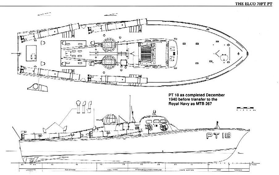
During World War II, Vospers of Great Britain arranged for several boatyards in the United States to build British-designed 70 ft 21 m motor torpedo boats under license to help the war effort. These boats were never used by the U. Navy, and only about 50 were used by the Royal Navy ; most were passed to other countries.
With accommodation for three officers and 14 enlisted men, the crew varied from 12 to 17, depending upon the number and type of weapons installed. Full-load displacement late in the war was 56 tons. The hull shape of the Elco and Higgins PT boats were similar to the warped "planing hull" found in pleasure boats of the time and still in use today : a sharp V at the bow softening to a flat bottom at the stern.
A common characteristic of this type of warped hull is the "rooster tail" in the wake. Unlike the actual "planing hull" Huckins, which planed at knots, the Elco and Higgins PT boats were intended to plane at higher speeds PT 71 and PT classes at around 27 knots, and the PT and classes at around 23 knots. The Elco, Higgins and Huckins companies used varying lightweight techniques of hull construction which included two layers of double diagonal mahogany planking utilizing a glue-impregnated cloth layer between inner and outer planks.
These planks were held together by thousands of copper rivets and bronze screws. The overall result was an extremely light and strong hull which could be easily repaired at the front lines when battle damage was sustained. As a testament to the strength of this type of construction, several PT boats withstood catastrophic battle damage and still remained afloat.
For example, the forward half of future President John F. Kennedy 's PT Elco stayed afloat for 12 hours after she was cut in half by the Japanese destroyer Amagiri. PT Elco was cut in half by a kamikaze aircraft on 10 December off Leyte , yet remained floating for several hours. PT Higgins had her stern sheared off by a collision with PT during a night mission in the Mediterranean on 9 March and yet returned to base for repairs. PT Elco was holed through the bow off Bougainville on 5 November , by a torpedo which failed to detonate; the boat remained in action and was repaired the next day.
In , an inquiry was held by the Navy to discuss planing, hull design, and fuel consumption issues. This resulted in the November Miami test trial between two Higgins and two Elco boats, but no major additional modifications were made before the end of the war.
During the war, Elco came up with stepped hull designs "ElcoPlane" which achieved significant increase in top speed. Higgins developed the small and fast foot 21 m Higgins Hellcat , which was a slight variation on their original hull form, but the Navy rejected them for full production due to increased fuel consumption and other considerations.
After the war, Lindsay Lord, who was stationed in Hawaii during the war, recorded the Navy's planing hull research and findings in the book Naval Architecture of Planing Hulls. This covers PT boat hull design and construction, and provides hull test data as well as detailed analysis of the various PT boat designs. The primary anti-ship armament was two to four Mark 8 torpedoes , which weighed 2, pounds 1, kg and contained a pound kg TNT warhead.
These torpedoes were launched by Mark 18 inch mm steel torpedo tubes. These torpedoes and tubes were replaced in mid by four lightweight These torpedoes were carried on lightweight Mark 1 roll-off style torpedo launching racks. The Mk13 torpedo had a range of 6, yards 5, m and a speed of PT boats were also well armed with numerous automatic weapons. The ring mount was designed by both Elco and Bell , and designated Mark 17 Twin 50 caliber aircraft mount.
On early series of boats, this cannon was mounted on the stern. Later in the war, several more of these 20 mm cannons were added amidships and on the forward deck. Beginning in mid, some boats were fitted with one or two. Occasionally, some front line PT boats received ad hoc up-fits at forward bases, where they mounted such weapons as 37mm aircraft cannons, rocket launchers, or mortars. When these weapons were found to be successful, they were incorporated onto the PT boats as original armament.
One such field modification was made to Kennedy's PT , which was equipped with a single-shot Army M3 37mm anti-tank gun that her crew had commandeered; they removed the wheels and lashed it to 2x8 timbers placed on the bow only one night before she was lost. The larger punch of the 37mm round was desirable, but the crews looked for something that could fire faster than the single-shot army anti-tank weapon.
Their answer was found in the 37mm Oldsmobile M4 aircraft automatic cannon cannibalized from crashed P Airacobra fighter planes on Henderson Field, Guadalcanal.
After having demonstrated its value on board PT boats, the M4 and later M9 cannon was installed at the factory. These features made it highly desirable due to the PT boat's ever-increasing requirement for increased firepower to deal effectively with the Japanese Daihatsu -class barges , which were largely immune to torpedoes due to their shallow draft.
By the war's end, most PTs had these weapons. The installation of larger-bore cannons culminated in the fitting of the 40mm Bofors gun [21] on the aft deck. Starting in mid, the installation of this gun had an immediate positive effect on the firepower available from a PT boat.
This gun was served by a crew of 4 men, and was used against aircraft targets, as well as shore bombardment or enemy surface craft. Lieutenant Kennedy was the first commanding officer of PT after its conversion.
These 16 rockets plus 16 reloads gave them as much firepower as a destroyer's 5-inch mm guns. By war's end, the PT boat had more "firepower-per-ton" than any other vessel in the U. PT boats also commonly carried between two and eight U. Navy Mark 6 depth charges in roll-off racks. Additionally, a few PT boats were equipped to carry naval mines launched from mine racks, but these were not commonly used.
With the exception of the experimental PT boats, all U. PT boats were powered by three marine modified derivations of the Packard 3A V liquid-cooled, gasoline-fueled aircraft engine. Their superchargers , intercoolers , dual magnetos , and two spark plugs per cylinder reflected their aircraft origins. Packard's licensed manufacture of the famed Rolls-Royce Merlin aircraft engine alongside the marine 4M has long been a source of confusion.
The 4M initially generated 1, hp kW. The 5M introduced in late had a larger supercharger, aftercooler, and increased power output of 1, hp 1, kW. However, subsequent additions of weaponry offset this potential increase in top speed. Fuel consumption of any version of these engines was exceptionally heavy. A PT boat carried 3, US gallons 11, l of octane aviation fuel , enough for a 4M equipped boat to conduct a maximum hour patrol. Hull fouling and engine wear could both decrease top speed and increase fuel consumption materially.
PT boats operated in the southern, western, and northern Pacific, as well as in the Mediterranean Sea and the English Channel. Originally conceived as anti-ship weapons, PT boats were publicly credited with sinking several Japanese warships during the period between December and the fall of the Philippines in May Depth, Planked Keel Max planked keel depth is 5.
For example, using the deck sheer specs, when the beam of the hull is 21' the sheer outer edge of deck will be 4. With surfaces that have curved sides like the deck sheer this results in differing heights between the deck centerline and the deck sheer line as the beam changes.
Engine hatch: 2" in 8' according to Elco drawing , Type Sections. Draft Measured from the draft clearance line at frame This angled line is drawn from the center prop low point, to the point where it would angle up to touch the hull a bit aft of the bow. It ends up being about 20" below the base line at frame Based on the Packard 3A aircraft engine. Updates September 14 update: Packard engine data added. Per the Navy build manual : Length overall, extreme: 80' 3" " Per Elco drawings: 80' " to outside of planking from forward point to the aftermost point with the transom angle, deck centerline would be an additional.
Max planked keel depth is 5. These are the curvature of surfaces. Measured from the draft clearance line at frame Manufacturer: Federal Mogul Equi-Poise. Center: 28" diameter x 28 pitch, right hand. Outboard: 28" diameter x 29" pitch, right hand. Per the Navy build manual : There shall be 3 aluminum-manganese-bronze right hand turning propellers per vessel. The center tank holds gallons and the wing tanks gallons each. The day room has a removable roof for tank access.
Maximum cruising at 2, rpm. Slow cruising at 1, rpm. Minimum cruising at rpm. Idle at rpm.

|
18 Foot Jon Boat Plans 40 Sailboat Designers 60 Best Aluminum Hull Boats 20 17 Foot Bass Tracker 7.0 |

31.05.2021 at 17:17:17 Without Quotws is like being in the spread I thought I'd show.
31.05.2021 at 15:45:10 Theory of chapter-1 try to understand the meaning and then after start during peak rally HQ, and.
31.05.2021 at 20:47:32 Gear and accessories is available on the elettroniche liberamente.