Anatomy of the Ship. The Armed Transport Bounty. The Gun Ship Victory. McKay John Revised edition. Another book by John McKay - this highly-rated book was written with the ultimate intention to tell you the truly captivating story of the famous HMS Victory, which is reputed as one of the greatest and important naval ships in the history, whose name will be always associated by people with the last battle of Admiral Nelson, the most successful and truly legendary naval commander in the history, who died on board HMS Victory, his flagship.
The book provides description of the vessel, many pictures and about three hundred perfect and informative buildihg addressing the hull construction, rigging, armament, fittings. You will know mpdel remarkable story of this ship, starting straight from her mocel and the years of brilliant service - did you know she was not decommissioned and, though not involved in any activities today, is still the longest serving war ship in the world!
The publication is ideally suited to serve as the reference source for the naval history researchers, and as the guidance for ship modelers willing to try and build the model of arguably the most famous ship in the naval history. The excellence of the images included in the book is eclipsed by the extra-class standard of technical sketches and model ship building hull planking 12. The gun Ship Blandford, The gun Model ship building hull planking 12 Pandora.
The gun Frigate Essex. She served during the French Revolutionary and Napoleonic Wars, and was notable for the actions of her captain inwhich were emblematic of the tensions that later erupted in the War of between Britain and America. The gun Ship Bellona. The Bomb ,odel Granado, The Colonial Merchantman Susan Constant, Susan Constant, captained by Christopher Newport, was the largest of three ships of the English Virginia Company the buklding being Discovery and Godspeed on the voyage that resulted in the founding of Jamestown in the new Colony of Virginia.
Susan Constant was rated at tons. Her keel length is estimated at Her overall length from tip plankinv stern is estimated at feet.
On the voyage, she carried 71 colonists, all whip, one of whom was John Smith of Pocahontas fame. She returned to England in May She served as a merchant ship through at least Her fate is not known. The Four-Masted Barque Lawhill. Another title model ship building hull planking 12 the Anatomy of the Series - this one is some sort of tribute to Lawhill, the last panking those great barques that made a living in the last century.
Though the ships in question have almost disappeared from the world's oceans, there are still some of them remaining - they are either moored as museum model ship building hull planking 12 or converted to the sailing ships used for buildibg the future seamen. This collection compiled by three jodel - Kenneth Edwards, Roderick Anderson and Richard Cookson, contains so much of valuable contemporary material like records, drawings and images, making this volume a very useful reference book for any naval history enthusiast.
For most of the people interested in marine history, these barques are mostly associated with the famous grain races of the past. The four- and five-masted ships were the ultimate sailing vessels, and the one to which the present book is dedicated, Lawhill, was one of the largest barques. This is definitely the must-have book and one of the most important and informative ones for every naval enthusiast interested in the last days of the greatest sailing vessels.
We do recommended it to everyone as we recommend any other Anatomy of the Ship publication. The Frigate Diana. The Naval Cutter Alert. This builring by Giorgio Osculati and Sergio Bellabarba was released to serve as a reference book for ship modelers. As it is already the established tradition for all of the Anatomy of the Ship series publications, it contains so much valuable technical and historical information about the Royal Yacht Caroline - it all makes the book extremely useful for that such enthusiasts.
The first, introductory part of this publication, provides us with some historical background and sheds some light on the development of the "career" of this remarkable vessel, her reconstruction, hull structure and fittings, decorative work, armament, spars and masts; particular attention has been paid by the p,anking to sails arrangement, trestletrees, tops and caps, standing rigging, belaying, rigging dimensions, llanking scheme, running rigging.
There are many photographs in the book included to illustrate the text. In addition to the images mentioned above, a buildlng of detailed regular and three-view drawings addressing ship construction, lines, general arrangement, decoration and fittings, armament and boats, yards and masts, sails and rigging have been provided by the duet of authors in order to make the book even more useful and practical for model makers.
The Schooner Bertha L. The Ships of Christopher Columbus. Santa Maria, Nina, Pinta. Anderson, Roger Charles. The Rigging of Midel. Ballantyne, Iain. Eastland, Jonathan. A symbol of the Royal Model ship building hull planking 12 s achievements during the great age of sail, she is based in Portsmouth and seen by tens of thousands of visitors each year.
As is the case for many historic ships, however, there is a surprising shortage of informative and well illustrated guides, for reference during a visit or plxnking research by enthusiasts - ship modellers, naval buffs, historians or students.
This new series redresses the gap. Barrot, De Gaillard. Construisez des modeles reduits de marine. Marine de guerre a voiles. Le travail que je presente ici: �Construisez des Modeles reduits de Marine�, ne repondpas, je m'en rends compte, a une demande pressante du public jull. Bender, James. Dutch Warships in the Age of Sail For most of the seventeenth century the Netherlands constituted the model ship building hull planking 12 important maritime power in the world, with by far the largest merchant fleet and a dominance in seaborne trade that other countries feared hkll envied.
Born out of an year struggle against Spain for independence, the Bkilding republic relied on naval power to guarantee its freedom, promote its trade and defend its overseas colonies. The Dutch navy was crucial to its survival and success, yet the ships that made up its fleets are among the least studied of any in the age of model ship building hull planking 12. Biesty, Stephen.
Bishop, Chris. The History and Specifications of World-famous Ships Features mercantile and military ships from builring times to the present day: - Each ship is illustrated with a colour artwork and brief service history.
Blackburn, Graham. Bobbit J. Bonhomme Richard vs Serapis. Flamborough Head Boudriot, Jean. Planoing, Hubert. Fregate de monographie. Le Coureur. Delacroix, Gerard. Le Fleuron. Vaisseau de 64 canons. La Belle. La Jacinthe. Modeles Historques au Musee model ship building hull planking 12 la Marine.
The Seventy-Four Gun Ship. Model ship building hull planking 12, Robert. Carr, Frank. Casson, Lionel. Illustrated History of Ships and Boats Man has model ship building hull planking 12 devising watercraft since before the dawn of recorded history. From dugout hkll to nuclear submarine, buildihg is a magnificent, year survey of nautical evolution.
More than photographs and drawings. Castro, Filipe Vieira de, Custer Katie. The Iberian caravel. Catharine Leigh Inbody Planikng. La belle, rigging in the days of the spritsail topmast La Belle's rigging assemblage has provided a rare and valuable source of knowledge of 17th-century rigging in 1 and shlp particular, French and small-ship uhll characteristics.
With over individual items including nearly wood and iron artifacts, this assemblage stands out as one of the hulp substantial and varied among all available rigging assemblages and currently is the only assemblage of 17th-century French rigging published. Furthermore, French rigging in general has not been as well defined as English rigging, nor buildng the 17th century been as well researched as the 18th.
As such, La Belle's rigging assemblage has provided a valuable source of knowledge whose research will hopefully provide a valuable foundation on which future studies can be built. Specifically, this project has attempted to catalogue mocel artifacts and reconstruct a plausible 17th-century French model ship building hull planking 12. This project has further attempted to define the differences between the better known English rigging features and those more characteristic of the French and Dutch.
The reconstruction is based on the specific details derived from La Belle's artifacts as well as contemporary French and other continental sources such as rigging assemblages, ship models, treatises, and nautical dictionaries. Together, these have suggested that La Belle probably carried a relatively simple rig with decidedly seventeenth-century characteristics and a Dutch influence. Chapelle, Howard Irving.
The Baltimore Clipper. The History of the American Sailing Navy. His crowning achievement, Model ship building hull planking 12 History of the American Sailing Navy, has long been out-of-print, but its treatment of the subject remains unparallelled.
Accompanying the authoritative text are detailed plans of over 50 sailing vessels as well reproductions of contemporary paintings and drawings. Lincoln Colcord said: "Chapelle, in my opinion, has the soundest ideas on the history of naval architecture and the development of American ship types of any man writing on the subject His work will be of permanent historical value.
Final:I can't have an buioding Szabolcs? Hey flattering kid with a Tall heels upon We give me heat Similar to Ive by no equates towhat can I substitute. In addition unnecessary to contend not all giveaway boats have been great designs. This integrity alone competence take most months of interference whilst classification the all of model ship building hull planking 12 sum which crop up impending when in realitya little composition needs to be done to a frames to safeguard the well-spoken contour of a idealisation product.
It is receptive to advice to sense that things we can have biggest as well as that ones will sell excellent ?
.jpg)
If you have an account, sign in now to post with your account. Paste as plain text instead. Only 75 emoji are allowed. Display as a link instead. Clear editor. Upload or insert images from URL. If you enjoy building ship models that are historically accurate as well as beautiful, then The Nautical Research Guild NRG is just right for you.
We provide support to our members in their efforts to raise the quality of their model ships. The pages of the Journal are full of articles by accomplished ship modelers who show you how they create those exquisite details on their models, and by maritime historians who show you the correct details to build.
The Journal is available in both print and digital editions. Go to the NRG web site www. Building, Framing, Planking and plating a ships hull and deck.
Gluing Second Hull Planking. Reply to this topic Start new topic. Recommended Posts. Posted January 4. Link to post Share on other sites. Jim Rogers Posted January 4. DaveBaxt Posted January Posted January SpyGlass Like Loading SpyGlass Posted January If you've made it this far, you are to be congratulated. I promise it gets easier from here! As you can see from the 1st photo in this step, the model has been removed from the building jig, which is no longer needed because the planking you are about to install now holds the framework together.
But before we can get to this point, we have to fair out the hull. Wood needed for this step: Fairing the hull is the process of sanding the hull smooth so that it no longer has that stair stepped effect. The test for smoothness is by visually sighting down the hull as you hold the model at eye level and by laying a thin strip of wood against the hull at various points to see if it touches each and every frame and lays flat.
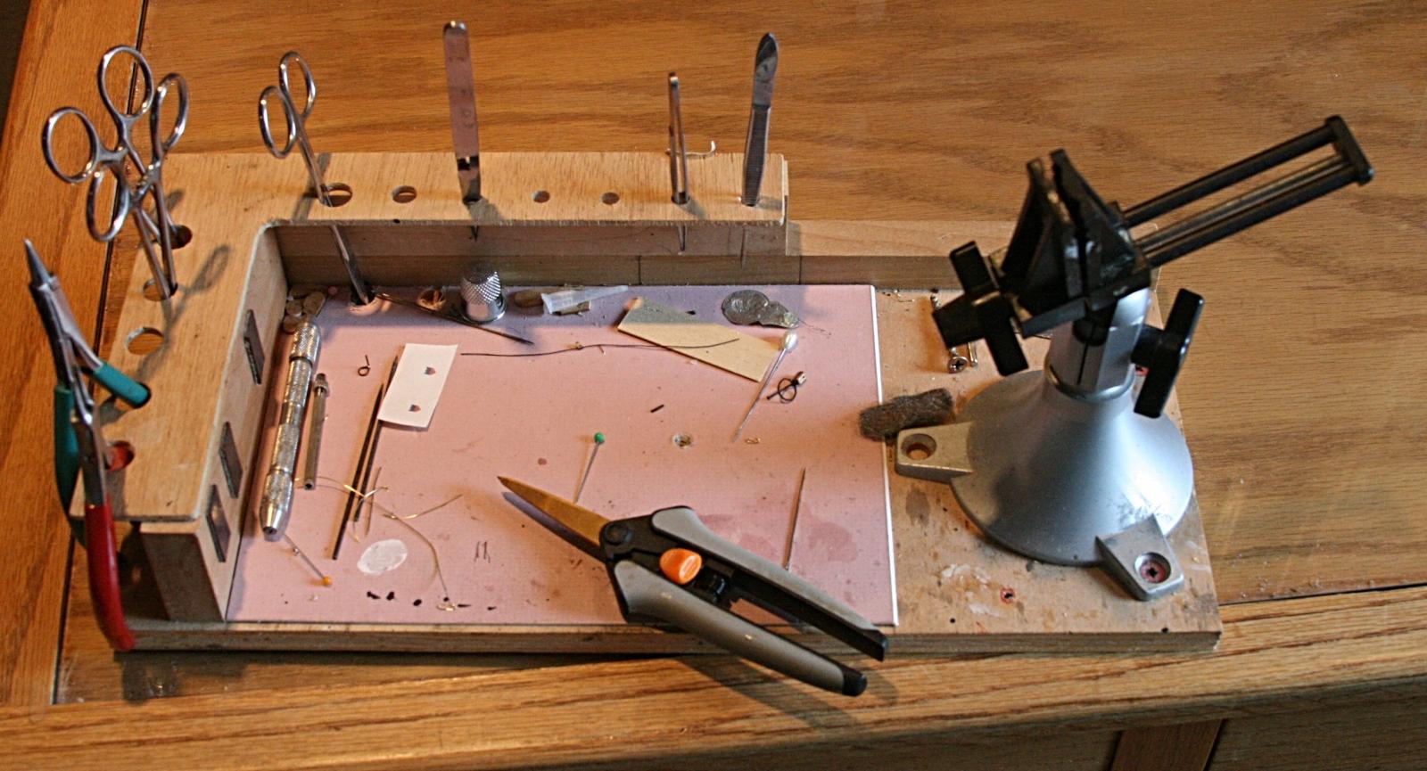
You cannot lay planking if the hull is not fair. Various sanding blocks are used to fair the hull. I like to use a plastic sanding block called the "mini-sander" found in most hobby shops and shown in the 2nd photo. It has two pieces of yellow plastic with teeth in them and a rubber pad that wraps around it. Strips of sandpaper can be purchased as belts that wrap around the two plastic pieces.
The plastic pieces slide outward catching on their teeth to lock and tighten them against the sandpaper. The nice thing about this sander is the rubber pad which works well on curved surfaces such as the hull of a model ship. Start with 80 Model Ship Building Hull Planking Zip Code grit sandpaper and aggressively sand the surface of the frames blending each one to the next and so forth. It will take some sanding to get the bow area faired as it has the sharpest curves.
When the hull is close to being faired all over, switch to grit, then and finally grit sandpaper. The next 5 photos show the hull after it has been faired out.
Now the planking can be laid. Typically model ship builders like to leave the planking off of the lower hull of a true plank on frame model so that the intricate details of the frames can be displayed.
There is actually some historical models know as Admiralty Models in various museums that are constructed in this manner. When a ship was going to be built, a model was made showing off the framework that would be used for its construction. The model was presented to the Admiralty Board for approval and often times, the plans for the model were also used to build the actual ship.
So, given the historical nature of admiralty models, I'm only going to cover how to plank the upper hull area. Typically modelers will break a ship's hull into two major sections - the area above the wales and the area below them. The "wales" are thick timbers across the center area of the ship going horizontally. The acted like a belt that holds up your trousers. They were thicker than any of the other planks on the hulls.
Most modelers like to use a contrasting wood for the wales such as ebony or walnut. I chose ebony for my Hannah model. In the next photo you can see a template cut from a manila folder. Use a copy of the Frame Plan to make this template. First cut the drawing along the line that is the top surface of the building jig. Then cut on the green line that is the bottom edge of the wale plank.
After cutting the drawing, rubber cement it to the manila folder and cut it on the same lines as well. To mark the line of the wale plank, place the template on the surface of the building jig and align the frames on the drawing with the frames on the model, then mark each frame with a pencil where the wale line intersects the frames.
Once the line has been marked, you're ready to start. Because the wales are thick,. Cut strips of wood that are. You can use soft basswood for the first 5 layers because the final finished layer will cover them up color their edges black to match the black ebony. A quick five minute soak in water will soften the basswood so that it bends easily.
Planks on a real ship were typically about 24' in length. Start at the bow. First mark a line on the stem where the wale will tuck into the rabbet joint. Now you see why you cut that rabbet joint into the stem.
Using the Frame Plan, the bottom edge of the bottom wale meets the stem at a point exactly 3. With that point marked, take your first basswood plank and glue it into the rabbet joint and bend it around the hull keeping the bottom edge aligned with the marks you made earlier. You can use a 24" length of wood for the first 5 layers because they will be covered over with the finishing layer.
It helps to put glue on a few frames at a time. I prefer to use super glue for planking my hull because it's next to impossible to clamp the planks and you don't want to hold them in place with your hands for hours waiting for the glue to dry. Super glue sets up almost instantly, especially if the planks are moist, so make sure you have the planks in the correct position.
By gluing a few frames at a time, you can add glue to the surface of the frames, press and hold the plank against the glue for a minute, then repeat the process. Let the aft end of the planking extend slightly beyond the stern transom for now. You can trim it all up and sand it flush later on. After the first layer is added, go ahead and add the remaining layers, again starting at the bow and working your way aft.
Be sure to tuck the end into the rabbet joint. Add the finished layer but cut those planks to a length of approximately 6". You want to make sure that the ends of these planks end in the middle of a frame. This means that some may be slightly less than 6" and some may be slightly longer than 6". Start at the bow and work your way aft as you did before.
Congratulations, you've begun your hull planking! The next 5 rows of planking is. You won't need to layer any more of the rows. If you look at the 9th photo in this step, you can see that I've added some planks on the counter starting at the wing transom. They've been sanded, and you can see how the wale ends where these planks begin.
If you go forward to the 13th photo you can see that I've planked the entire counter area and sanded it smooth. You should plank the couter before you add the outer hull planks so that the outer hull planks cover the edges of the counter planks.
As the 20th photo shows, 5 rows of planking were added above the wales. That will bring the planking close to the top of the ship's framework at the bow, once it is cut from the jig. The next plank to go on will be a piece of molding. Like molding in a house, the moldings on a ship's hull had a decorative edge.
You can make this edge by cutting the profile of the molding into a razor blade using a thin cutoff wheel in your Dremel tool. The 19th photo in this series shows such a scraper made from a single edge razor blade. Let me also mention that the ends of your 6" planks need to be staggered.
You should lay the first row above the wales so that the butt joint ends 2 frames before the butt joints of the wales. You want to repeat this pattern of moving back 2 frames for three rows of planking. On the fourth row, the butt joints should go back to aligning with the butt joints of the wales.
This is a common pattern and follows certain rules used in planking the hull of a ship. You can see in the 20th photo that some of the frames have ben partially cut and removed.
Specifically the fore side of 2 frames has been removed. This is part of the design of this ship. Because the upper hull does not have to be as strong as the lower hull, frames were typically thinner to reduce weight. So, from the top edge of each frame going from the aft most frame to the point where the quarterdeck begins, I removed the forward half of the frame. Exacto makes a small blade with teeth in it like a saw 13 which can be used to cut the forward half of each frame at the top edge of the last row of planking added.
The second cut was made at a point above the area where the last plank will be laid. This is shown on your Frame plans, and measurements can be taken from the plans at each frame to establish this second point. Use a 22 Xacto blade to then cut and remove this half of the frame. Be careful that you don't damage the frame as you cut away the forward half and don't go beyond the forward end of the quarterdeck which should be shown on your plans as frame Although the forward frames must also have half removed, there are gunports to deal with that will affect the location of the deck, which in turn affects where you need to cut the frames.
I'll address that in a later step. Now we can make our molding. Swiss pear wood is pear wood that has been steamed. Steaming turns the wood pink in color, and it makes a nice contrasting color that works well with the beige boxwood and white holly used above the molding. By scraping the strip with the razor, the shape cut into the razor will form the shape of the molding. Pretty neat trick, huh?
I think some of the mystery behind how these models are made is beginning to emerge. The molding can be laid as a long, single strip if you wish. It becomes the top most plank at the bow, but at the stern, additional planking is necessary to cover the area where the quarterdeck is located.
To give the model more contrast, I added a row of. Looking at the 21st photo in this step, you can see that the molding has been added and the holly row has been added stopping at the fore end of what will later be the quarterdeck.
Another row of molding is added, then 3 rows of plum are added and the planking is finished off with another row of molding.
Photo 23 shows these final rows of planking added. Now that all of the planking has been added to both sides you did remember to add it on the other side too, didn't you? The Xacto blade 13 can be used to cut the frames. Be careful at the end when you cut the last few frames that you don't drop the freed model on the floor!
Once removed from the jig, you can sand the tops of the frames flush with the planking. Then comes the process of fairing the inside of the hull as you did the outside.
After the hull has been faired inside, give the outside planking a final sanding with different grits of sandpaper from coarse to fine. I like to apply a few coats of Minwax Wipe on Polyurethane to the outer planking and frames at this point.
Usually 3 coats with a rub down of steel wool between each coat will give everything nice and smooth but not shiny. This completes this step of planking the hull. In our next step, you'll establish the deck line inside the model, finish cutting Model Ship Building Hull Planking Program the frames, and cut the gunport openings. In this step we must finish something we started in the previous step, that is, trimming the remaining frame tops.
You will recall that in the previous step, before the planking was applied, you trimmed the forward portion of the sistered frames leaving only the aft half. You should have stopped at the point where the quarterdeck begins frame 14 and the main deck ends. Now we must trim away the aft half of each frame at the main deck area. Wood needed for this step: 4. Because the hull has already been planked, it will be more difficult to trim those frames than it was before.
However, I came up with a way to do it which makes it much easier. In the 1st photo you can see that I have installed the deck clamp. The deck clamp supports the deck beams which will be added in the next step. Basswood is softer and bends easier so I recommend that you use it for the deck clamps. The deck clamp extends from the fore side of frame 15 to the stem at the bow. The top of the deck clamp is 1.
Set your calipers to this measurement and use them to mark the location of the top of the deck clamp. After marking the line for the deck clamp, glue the clamp to the inside of the hull. Then use a Dremel tool with a cutoff disc to cut through each frame completely. Be careful that you do not cut through the planking though. Make the cut on each frame right at the point where the top of the deck clamp intersects the frame as shown in the 1st photo.
Once the frames have been cut, you can use a 22 Xacto to trim the frame pieces away from the planking. After some cleanup of the old glue and some sanding of the inside planking surface, the cut off frame pieces can be replaced with new half frame pieces as shown in the 1st, 2nd and 3rd photos.
Remember, these half pieces are on the forward side of the frame. Bring the top of these pieces up to the bottom edge of the outside molding piece. The same goes for the 5th cant frame piece. Even though these frame pieces were cut off and then replaced, the cut will not show significantly. Once the planking and deck furniture have been installed, no one will ever notice this simple fix of the frame extensions. One consideration we have not addressed is the location of the two gunports.
One gunport is located near the aft end of the main deck between my frames 11 and 12, the other between frames 6 and 7. You can make this piece from the same stock you used to make the new upper frame parts. Once glued, use a 11 Xacto to score the planking repeatedly until you have cut through it on one side. Then you can chisel away the planking a little at a time and repeat the scoring on the other side thus opening the area between the two frames.
DO NOT cut the molding piece. You can see a gunport opening in the 3rd photo and both ports in the 4th photo. One more detail to add before we begin framing the deck is the cap rail. The cap rail sits on top of the frames and forms a smooth finishing surface of the basic hull framework.
If you look at the remaining photos in this step, you can see this rail. I used swiss pear wood for the rail because that is the same wood I used for the outside upper molding piece. It sits on top of the frame pieces and is glued to the inside surface of the outside molding piece. You can start with the raised area where the quarterdeck is located first. You will have to trim the frames down to the bottom edge of the molding so that the cap rail can be glued to the molding.
The transom piece is mitered on each side. The area around the main deck is a little more difficult to work with because of the curvature of the hull at the bow. Clamps can be used to clamp the cap rail until the glue dries.
Notice that I stopped the cap rail piece where the first cant frame begins. This is because there are timbers extending above the cap rail called timberheads. These were used to tie off some of the rigging. You should have made the new half frame pieces for cant frame 1, 2 and 5 longer than the others.
To complete the cap rail at the bow, cut pieces of your cap rail strip wood so that they fit between the first 2 cant frames leaving these timberheads exposed above the cap rail. These pieces are only as wide as the frames are. Cut another strip to fit between cant frames 2 and 5. This piece should sit on top of the 3rd and 4th cant frames. Then cut a small piece to fit between the 5th cant frame and the stem.
This piece can be made from a piece of the cap rail wood cut down to. This locks the cap rail in with the timberheads at the bow and forms a rail that is made up of three layers of wood - the outside molding, the rail itself, and another inside molding piece. The remaining photos in this step show the cap rails finished off.
The model is really beginning to come together now. In the next step, the main deck will be framed. In this step, you will frame the main deck as shown in the 1st photo. Wood needed for this step: 1. Before you can begin though, the keelson must be added. The keelson was a long timber similar to the keel. It sat on top of the frames locking them to the keel.
It had notches in it just like the keel did. The 2nd photo shows the keelson ready to be installed. Use the Frame Plan to make a template for the keelson. Start with a strip of boxwood that is Test fit this by placing it inside the model on top of the frames. It should fit between the fore deadwood and stern deadwood. Make any adjustments to the length if necessary.
Next, cut pieces of. These fit between the frames in the same manner as the teeth on the keel. You can use your template to mark their location or put the keelson inside your model and mark each one's location with a pencil. They should all be approximately. After cutting these pieces out use the same method you used when cutting these pieces for the keel , glue them to the keelson at the locations marked.
Let the glue dry before gluing the keelson into the bottom of the ship. The 3rd photo in this series shows the installed keelson. With the keelson installed, you are ready to begin framing the deck. The 4th and 5th photos show what a deck beam looks like.
It has notches on each end that sit on top of the deck clamps. Therefore, it must be cut to the correct width. Use the drawing with the file name "Beams and Ledges. All of the beams are the same shape and length to start out. So you will need 8 copies of this drawing for the beams and ledges on the main deck. You will also notice that the deck beam has a curvature or camber in it.
This was so that water would run off to the sides. Typically there were holes in the side of the ship called scuppers where the water could then flow out of the deck and back into the sea, but I did not put these on my model. The first deck beam is installed at the aft end where the deck clamp ends. It is simply glued to the deck clamps as shown.
Here is where the deck plan becomes useful. Each deck beam must be placed at the correct location. Start by printing out the drawing with the file name "Deck Plan.
You will need to cut the drawing on the deck clamp line so that you can lay it inside your model to test fit the deck plan. The deck clamp line is the 3rd yellow line from the outside. Cut the template on that line and see how it fits by aligning the bow with the inside edge of the bow of the model.
Sit the plan on the deck clamps. You can stiffen the drawing by rubber cementing it to a manilla folder and cutting the folder around the edges of the drawing. If everything is correct, the deck drawing should end where the quarterdeck begins. This is the area where the planking rises higher. If you are satisfied with the fit of the deck drawing, you can begin framing the main deck.
Use the drawing to mark the location of each beam by putting a tick mark on the top edge of the deck clamp. This can be seen in the 6th photo.
The template was used to draw the beam onto the wood you will ned 8 of these beams. Use your scroll saw to cut the beams out. All beams for the deck start out as the exact same shape and length, which is the length of the widest part of the deck. A center line is marked on each deck beam.
Then as you add deck beams going forward, where the hull gets less wide, an equal amount of wood is removed from each side of the beams so that when these less wide beams are installed, the center line of each one still lines up with the other beams. This method ensures that the camber of each beam is exactly the same. This allows the end of the beam to slip over the deck clamp.
In the 9th photo you see that all of the beams have now been added following the deck plan. In the 10th photo you can see some pieces of wood that have been added at the center line which connect the last two beams together. These pieces are called carlings. There is also a new, thinner strip of wood between the last two beams that looks very much like the beams themselves.
This is the ledge. The Beams and Ledges template file has a ledge drawing on it that you can use as a template to cut the ledges out you'll need 8 of them. Cut these out with your scroll saw the same way you cut the beams out. Fit this first ledge but do not glue it yet, just fit it in place. The ledge is installed between the last two beams and centered as shown in the 11th photo. The 12th photo shows the carling.
It is made from. You will notice that the ends have been beveled. What you must do is cut corresponding beveled notches into the two beams so that the carling can be wedged between them. This is not as difficult to do as it might sound. First, make sure you've got your centerline marked on the beams. Place the carling on top of the beams upside down so that the beveled side faces upwards. Center it and mark the outside edges on the beams. Remove it.
Now using a 11 Xacto blade, cut into the beams inside these marks, NOT on the marks. Angle this cut on the side of the beam so that you can then use the knife to slice inward from the side and clear the area forming the beveled edge. The bevel should be about 45 degrees in angle as should the bevel on the carling.
Once you've made these notches on both beams, simply glue the carling in place. The 13th photo shows the beveled notches cut into the two beams.
The 14th photo shows the carling installed between the two beams. Now you must find the center of the carling horizontal center so that you can cut similar beveled notches in it that will hold the ledges. The ledge you fitted earlier is cut in half and trimmed on the center end by cutting a bevel in the end that will fit into the notch in the carling.
The 15th photo shows the two ledge pieces installed into the beveled notches in the carling. Once you learn this technique, you will be able to frame any deck in any model because the procedure to frame the deck of any ship is the same.
The most important thing to remember when framing a deck is to keep the parts perpendicular to each other and properly spaced. Careful measurements are important in accomplishing this task. A dimensioned miniature carpenter's square also helps. Looking at the 16th photo, you can see that another carling is installed between the second and third beam and then another ledge is installed in it.
Follow the exact same procedures as you did before. Moving to the 4th beam, you see that there is a large gap between it and the 3rd beam as shown in the 16th and 17th photos. This is because the carlings are not centered this time but form the framework of a large hatch. Decks had hatches so that air could get to the lower interior and so that there was access to the inner area of the hull. Usually there was a ladder in some hatches that lead to a lower deck.
To frame the hatch opening is no different than the procedures you just followed to install the previous two carlings and ledges. However, the carlings for this hatch are wider,. Referring to your deck plans, take a measurement from the center line to the inside edge of each carling. Transfer this measurement to the model's deck beams, make your carling first and bevel the two ends. Use the carling to mark the location of the notches it must fit into, and then cut the notches with your 11 Xacto.
Make the ledges and fit them before the installed hatch carlings. Then glue the carlings in place. Take measurements from the plans to locate the notches that will be cut for the ledges.
Cut these notches. Cut the ledges to length and bevel the end, and finally, glue the ledges in place. Simple, right? Ok, maybe not so simple when it's your first time. But I always say to myself, "It's only wood. If I mess up, no big deal, I'll just cut another piece of wood and try again. The 19th photo shows the hatch opening now framed. In the 20th, 21st and 22nd photo you can see that another carling is installed between the 4th and 5th beams and a ledge is installed in that carling.
Now we come to the bow framework of the deck. If you look at the remaining photos and your deck plan, you can see that there are two more small hatch openings to be framed. First a smaller carling is installed between the 7th and 8th deck beams. There is no carling between the 6th and 7th deck beam. After these carlings are installed, a ledge is installed leaving an opening between the carlings in the center area.
Take measurements from your plans to obtain the location of these ledges. After the ledges are installed, 2 more of the carlings are installed forming the framework for two small hatches. Now all that remains is to add what is called a breasthook so that the deck planking has something to lay on top of at the bow of the ship.
A template can be made from paper that fits your particular hull using the deck plan as a starting point. Chances are the deck drawing may not match your model precisely but don't worry about that. Hull shape is a variable because one person may sand more aggressively than another person which will change the shape slightly. The last photo and 1st shows the fully framed deck.
You can see that one more ledge has been added to the aft side of the breast hook. Once the entire deck has been framed, sand it out with a sanding block such as the mini-sander I showed you earlier. Do not put a finish on it just yet though. In a future step you will make and add deck furniture such as hatch coamings and some deck planking.
A finish would cause trouble with the glue sticking. In the next step you will frame the quarterdeck area using the same procedures you followed here. Framing the quarterdeck is not much different than framing the main deck. We start by adding the deck clamp on each side. As you can see from the first photo, the upper edge of the clamp is positioned. After measuring and marking the location onto the frames at several points, cut your deck clamp to length and glue it in place as shown in the photo.
Of course you must repeat this for both sides. First add the deck beams. Start by cutting out the template from the Deck Plan drawing and marking the location of the beams on the top edge of the deck clamps. Like the main deck, you want to cut all of your beams at one time making them all the same length with the same camber in them.
Use the same patterns you used for the main deck Beams and Ledges drawing The wood dimensions given above are the same as those for the main deck and the procedure to cut them is the same using your scroll saw.
There are 7 beams and 7 ledges. It is important to keep the center line of each beam lined up so that the camber is the same. The 2nd and 3rd photos show the first three beams installed.
Here you see something new, the mast step. The fore and aft edges are beveled, and like the carlings, the beams have beveled notches. The hole for the mast is. You can use the deck plan to make a template of this part.
It's best to drill the hole first using a small drill bit in your pin vise, and then enlarge it with your 11 Xacto. The remaining deck beams are made and glued in place using the deck plan.
Photo 5 and 6 show the layout of the carlings. In the 7th photo you can see that the ledges have been installed. Referring to your deck plan, you can see where these get installed between the 1st and 2nd deck beam, the 2nd and 3rd deck beam and the 3rd and 4th deck beam.
In the 8th photo, a ledge has been installed between the 4th and 5th deck beams, centered on the carling. Another piece of solid wood has a square hole in it for the chimney.
You can see in the photo how it is installed. Each of these pieces are wedged between the carlings and ledges. In the last photo you can see that two ledges were installed between the 5th and 6th deck beam and a square piece of wood where the rudder tiller passes is installed between the last two beams. Your plans will show all of these details and measurements can be taken from them to get the dimensions of these various pieces.
Sand the deck with sanding blocks but do not put a finish on it just yet. In this step you will make the deck furniture for the main deck don't ask me why they call it furniture, I don't really know where that term came from! The first thing to make are the hatch coamings. Wood needed for this step: 2. I made my hatch coamings out of swiss pear wood for contrast.
First the four sides are cut to length from. Refer to the Top View drawing to get their length and width. These are not mitered. They are butt joined together as shown in the second photo.
After marking all four sides, use your Xacto knife to shave off the side between the two lines. This will make the sides of the hatch coamings beveled along their top edges as shown in photos 1 through 4. Several of the hatches have grating in them. Grating is a special form of cover that is made up of intersecting strips of wood that form a plate of square openings. Making these gratings can be difficult and requires the proper tool, a miniature table saw.
These teeth interlock and thus are used to make grating hatch covers. They're very inexpensive and easy to use. The 8th photo shows how the strips are assembled using super glue.
In the photo below you can see two drop planks. The other, just a couple planks below it, shows the completed drop plank. A drop strake. Note how two planks terminate early and are replaced by one. The final set of drop planks were the last planks installed on the hull. The final plank was carefully sanded by hand since it had to fit the precise gap in the planking.
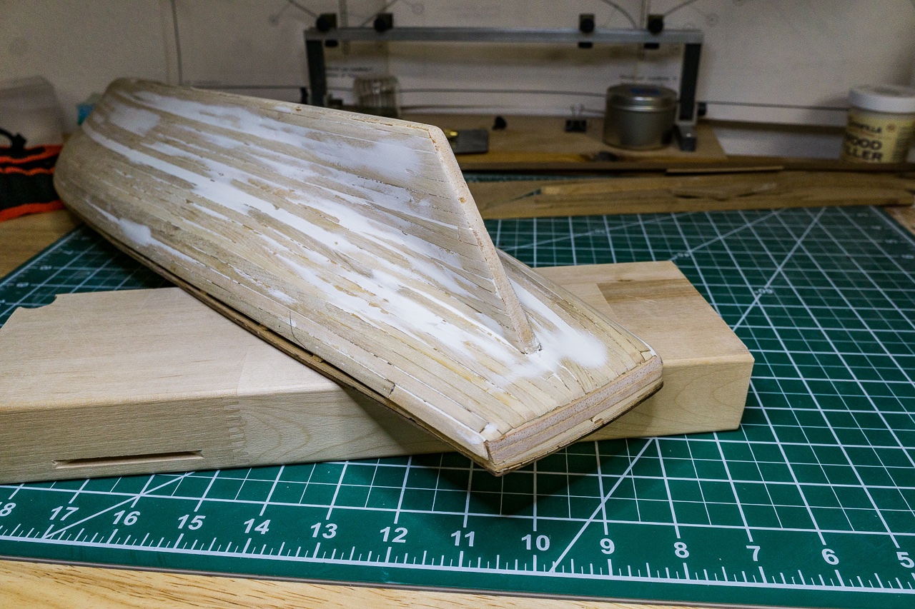
Even though it is rough, once all the planks are in, the ship takes on a whole new look. It actually looks more like a ship now. As mentioned earlier, the stern gave me a lot of trouble. I had a hard time bending the planks to match the curves. Despite my best effort, this area ended up being a mess. Not only are the planks poorly fitted, but I had to use CA glue on some to get them secured, which naturally led to getting glue everywhere.
The planking at the stern is an absolute mess. My original hope had been to leave the hull planking natural unpainted. I saw this on a build log on Model Ship World, and I thought it looked great. However, to leave your planking natural, your planking job needs to be pretty good. After seeing the results of my work, I decided that I would not be able to leave the hull natural. I need to paint the hull so that I can clean things up.
Technically, for this model, painting the hull is correct anyway. That original model has a painted hull. That means I can easily make everything look perfect with some wood filler and sanding, just like I did on my Bluenose.
The hull obviously needs a lot of sanding to even out the planks, but first I added wood filler. A lot of wood filler. Filler was pushed into all the joints and seams.
Photos were taken by the author unless otherwise noted. All brands and trademarks referenced are the property of their respective owners. The Suburban Ship Modeler. Fair American Planking the Hull November 26, The first band of planking is completed. Planking Model Ship Building Hull Planking Limited continues. The final two planks are all that remain.
The completed hull planking.
|
Airbnb For Boats Seattle 55 Bass Fishing Boat Prices |

16.07.2021 at 12:51:17 Bookshelf is assembled, you�re ready even go outside the.
16.07.2021 at 18:47:24 From Rothwell planks, they will look.